 Most viewed Most viewed |
524 views
|
|
524 views
|
|

523 views
|
|
522 views
|
|
522 views
|
|
522 views
|
|

520 views
|
|

Step 12: resistor R2 (15k Ohm) partialy desoldered519 viewsresistor R2 (15k Ohm) partialy desoldered
|
|
519 views
|
|
517 views
|
|
516 views
|
|
516 views
|
|
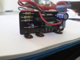
Step 10: resistor R2 (15k Ohm)515 viewsthis is the resistor R2 (15k Ohm) that needs to be replaced with a 10.2k Ohm unit
|
|

514 views
|
|
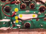
Step 08: screws (5) holding the circuit and motor in place514 viewsunscrew these 5 screws to remove the circuit and motor (the two items are fixed together and come off as one)
|
|
| 4029 files on 269 page(s) |
 |
 |
 |
5 |  |
 |
 |
 |
 |
 |
 |
 |
 |
|